Acronyms in the energy industry
Do you speak energy? Opoura’s energy glossary from A(FRR) to Z(NE)
Educational content
September 24, 2025
8 min read
In energy, as in many other industries, too, acronyms and abbreviations are useful tools that help us communicate quickly and clearly. But for those new to the industry or working across different roles, the number of acronyms can be overwhelming and even confusing.
In this educational piece, we break down some frequently used acronyms from the energy industry to help you understand their meanings and place in a broader context.
What are FCR, aFRR, and mFRR?
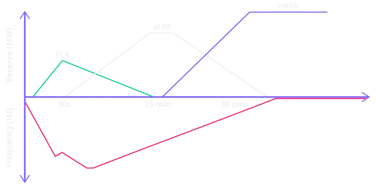
FCR, aFRR, and mFRR are three key types of balancing reserves that Transmission System Operators (TSOs) use to maintain stability of the electrical grid. If imbalances occur between the electricity supply and demand, the reserves are gradually activated to manage the imbalance and keep the system frequency at an acceptable limit.
FCR (Frequency Containment Reserve) is the first line of defense or primary reserve. This means, it is activated automatically within seconds when the system frequency deviates from its nominal value. It works locally and independently, with generators or other flexible assets automatically adjusting their output to contain the frequency deviation. FCR stabilizes the system until slower reserves can take over. It’s essential for immediate grid reliability and is always available in the background.
aFRR (automatic Frequency Restoration Reserve) is the secondary reserve. Like FCR, it also activates automatically, however with a slightly longer response time, typically within 30 seconds to a few minutes. Unlike FCR, aFRR is centrally controlled by the TSO through automatic signals sent to participating units. Its key function is to restore the system frequency to its target value and to correct any imbalances in scheduled energy exchanges between countries or control areas. aFRR plays a critical role in maintaining both system stability and cross-border coordination.
mFRR (manual Frequency Restoration Reserve) is the tertiary reserve. It is activated manually by the TSO when larger or longer-lasting imbalances occur. mFRR usually comes into play after 15 minutes or more and is often used to replace aFRR once the immediate issue has been handled. It is also used during periods of high system stress or when unexpected events require additional reserves. mFRR is typically activated through a bidding process in balancing markets, which makes it a flexible tool for ongoing grid management.
The importance of these three reserves continues growing with the increasing share of hybrid renewable energy sources, as they are less predictable. Therefore, ensuring sufficient reserve capacity at all times is crucial for grid reliability.
What do FID, EON, ION, and FON mean in a power project?
In the lifecycle of a power-generating project, multiple key milestones define the journey from investment to full commercial operation. Among these milestones are FID (Final Investment Decision), ION (Interim Operational Notification), EON (Energization Operational Notification), and FON (Final Operational Notification). Each of them marks important technical and regulatory checkpoints that determine when and how a project can connect to the grid and begin delivering electricity.
FID (Final Investment Decision) is the point at which the project owner or investor commits to building the power plant. This decision is based on detailed technical, financial, and legal analysis and often follows successful permitting and early-stage grid connection planning. Once FID is reached, the project enters execution, encompassing engineering, procurement, and construction (EPC).
From this point forward, the project proceeds through a series of technical and operational steps, culminating in grid integration under the oversight of the Transmission System Operator (TSO).
EON
EON (Energization Operational Notification) follows when the plant is technically ready to be energized and physically connected to the grid. This notification enables actual electrical energization of the facility, enabling it to undergo testing, synchronization, and performance verification procedures.
ION
ION (Interim Operational Notification) is typically issued after construction and before full commissioning. It allows the power plant to begin operating under specific conditions, usually limited output or temporary arrangements, while final tests and compliance verifications are still pending. This is not yet a full commercial operation, but it permits partial energization and early-stage grid support under controlled terms.
FON
FON (Final Operational Notification) is issued once the plant has met all technical and regulatory requirements. This includes successful completion of grid compliance testing (e.g., frequency response, voltage control, fault ride-through capabilities), system integration checks, and any obligations set by the TSO. With FON in place, the plant is fully authorized to operate commercially and deliver power to the grid at its contracted capacity.
Together, EON, ION, and FON represent the structured stages through which a generation asset moves from a construction site into a certified, operational energy producer. Each step helps ensure that new capacity is safely and reliably integrated into the grid.

Simulation types RMS vs EMT – What is the difference?
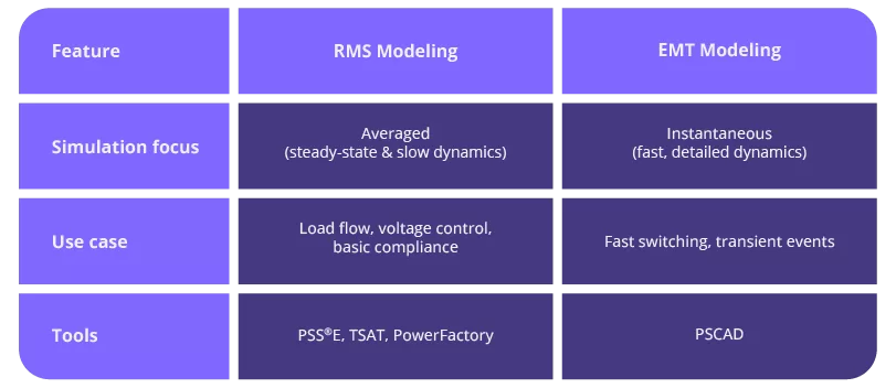
RMS and EMT are simulation types. The two terms refer to different types of power system modeling and analysis, each with specific use cases depending on the technical complexity and requirements of the grid. And understanding the difference between them and how simulation tools like PSCAD, PSS®E, and DIgSILENT PowerFactory relate to them is essential for anyone involved in connecting generation assets to the power grid.
RMS
RMS (Root Mean Square) models are simplified representations of power systems that simulate electrical behavior using averaged values over time, typically one or more cycles of the power frequency (e.g., 50 Hz or 60 Hz). These models focus on the steady-state and slower dynamic behaviors of electrical networks. RMS simulations are faster and computationally efficient, making them well-suited for large-scale studies such as:
- Load flow (power flow) analysis
- Stability assessments
- Planning and operational studies
- Voltage and frequency control evaluations
Hence, RMS models are often used in standard grid code compliance studies unless the system or equipment being modeled requires more detailed behavior to be captured.
The two terms refer to different types of power system modeling and analysis, each with specific use cases depending on the technical complexity and requirements of the grid.
EMT
EMT (Electromagnetic Transient) models, on the other hand, simulate the instantaneous values of voltages and currents at sub-millisecond time steps. This means that EMT simulation captures very fast and detailed electrical dynamics, including switching events, control system interactions, and converter behavior under fault conditions. EMT modeling is essential for:
- Grid-forming or grid-following inverter analysis
- High Voltage Direct Current (HVDC) systems
- Wind, solar, and battery storage systems with power electronics
- Weak grid interconnections
- Protection system coordination and fault studies
As the grid becomes more inverter-dominated, TSOs increasingly require EMT-based validation for certain grid code compliance studies.
How do PSCAD, PSS®E, and TSAT software fit into this?
PSCAD, PSS®E and TSAT are software tools used to simulate and analyze power system behavior. Each software tool is optimized for a specific modeling approach:
- PSCAD (Power Systems Computer Aided Design), is a leading tool used for EMT simulations. PSCAD allows detailed modeling of power electronics, converter control systems, and transient phenomena with high fidelity. It is the preferred tool for validating grid compliance of wind turbines, solar inverters, HVDC links, and BESS systems in weak grid conditions or when fast transients need to be captured.
- PSS®E (Power System Simulator for Engineering), is one of the industry’s most widely used tools for RMS-based studies. It supports load flow, dynamic stability, and fault analysis on large power systems and is commonly used by TSOs, utilities, and consultants for traditional generation and transmission planning.
- TSAT (Transient Security Assessment Tool) is also an RMS-based simulation tool but focuses more on real-time dynamic security assessments and contingency analysis, especially in large interconnected grids like those in North America.
- DIgSILENT PowerFactory (Digital Simulation and Electrical Network Calculation) is a power system analysis software used to model, simulate, and optimize electrical networks. It supports studies such as load flow, short-circuit, stability, and protection analysis, helping engineers design and operate reliable and efficient power systems.
These were a few detailed descriptions and definitions of some frequently used acronyms in energy. But there are many more. Energy glossary – the acronyms and abbreviations you will likely come across:
A
aFRR – automatic Frequency Restoration Reserve (secondary reserve)
B
BESS – Battery Energy Storage System
BRP – Balance Responsible Party (trader)
C
CapBank – Capacitor Bank
D
DSO – Distribution System Operator
E
EON – Energization Operational Notification
EMT – Electromagnetic Transient
ENTSO-E – European Network of Transmission System Operators for Energy
EPC – Engineering, Procurement, Construction
F
FAT – Factory Acceptance Test
FCR – Frequency Containment Reserve
FERC – Federal Energy Regulatory Commission
FID – Final Investment Decision
FON – Final Operational Notification
G
GIP – Generator Interconnection Procedures
GOP – Generator Operator
H
HCU – Hybrid Control Unit
I
ION – Interim Operational Notification
IPP – Independent Power Producer
J
Joule
K
Kilowatt-hour
L
LFC – Load Frequency Control
M
mFRR – manual Frequency Restoration Reserve (tertiary reserve)
MVA – Megavolt-amperes
N
NCC – Not Centrally Controlled (unit)
NERC – North American Electric Reliability Corporation
NESO – National Energy System Operator
O
OT – Operational Technology
OEM – Original Equipment Manufacturers
P
PPC – Power Plant Controller
PV – Photo-Voltaic
PoC – Point of Connection
PSCAD – Power Systems Computer Aided Design
PSS/E – Power System Simulator for Engineering
PtX – Power to X
Q
Reactive Power
R
RMS – Root Mean Square
RTO – Regional Transmission Organizations
S
SCADA – Supervisory Control & Data Acquisition
T
TSAT – Transient Security Assessment Tool
TSO – Transmission System Operator
U
UAT – User Acceptance Testing
V
V – Volt
W
WTG – Wind Turbine Generator
Z
ZNE – Zero Net Energy (also Net-Zero Energy)